Truss-rail ventilation rail mounting P.THG25-42R
We are happy to help you with making a calculation
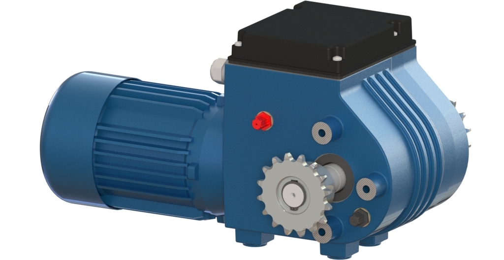
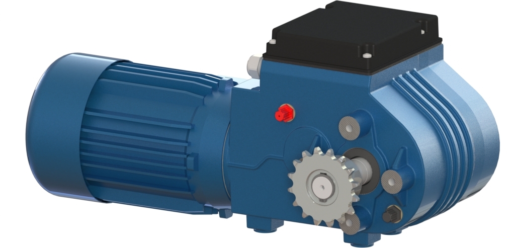
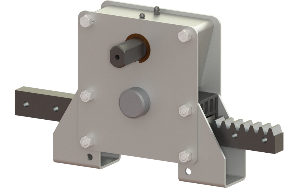
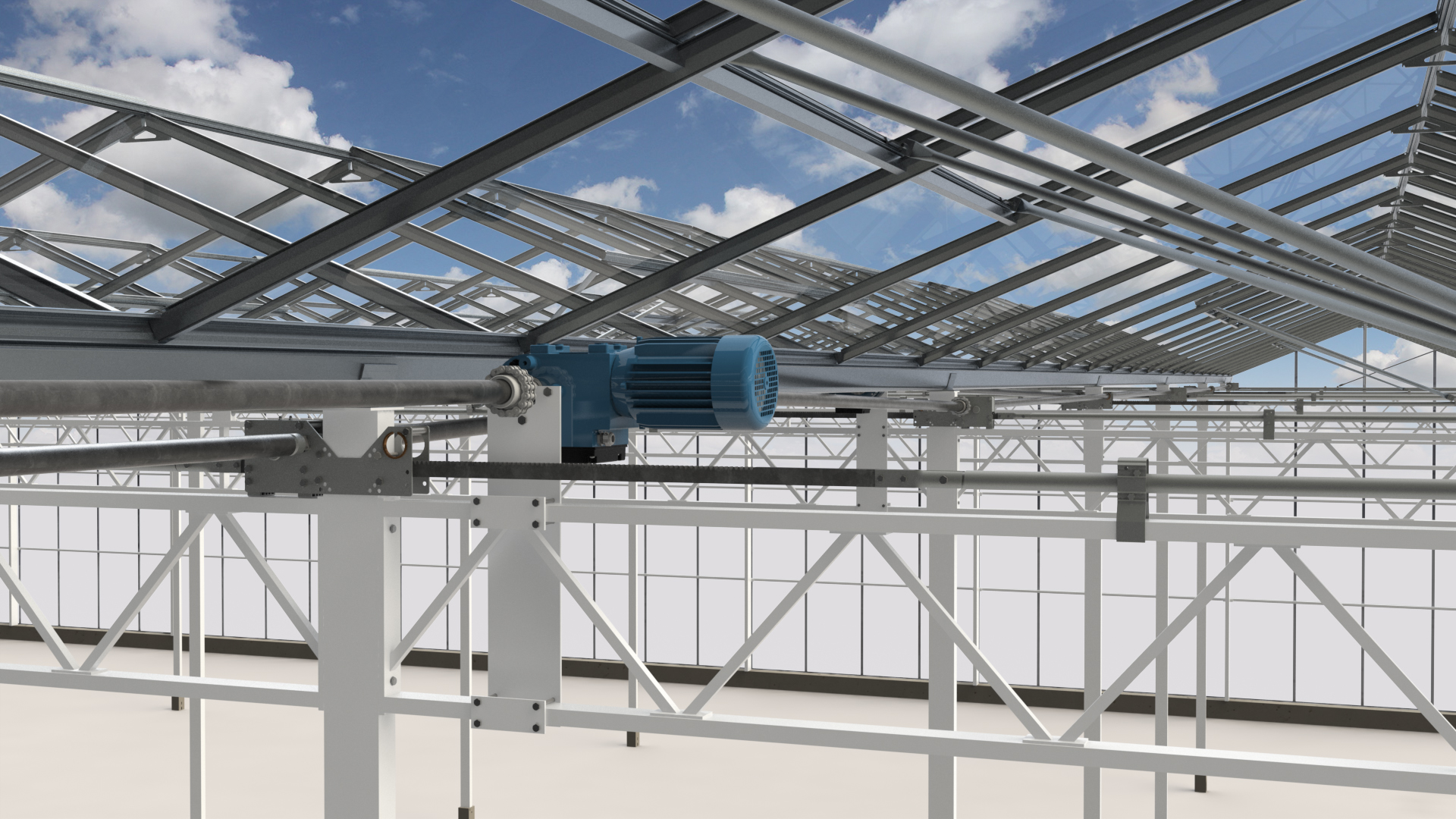
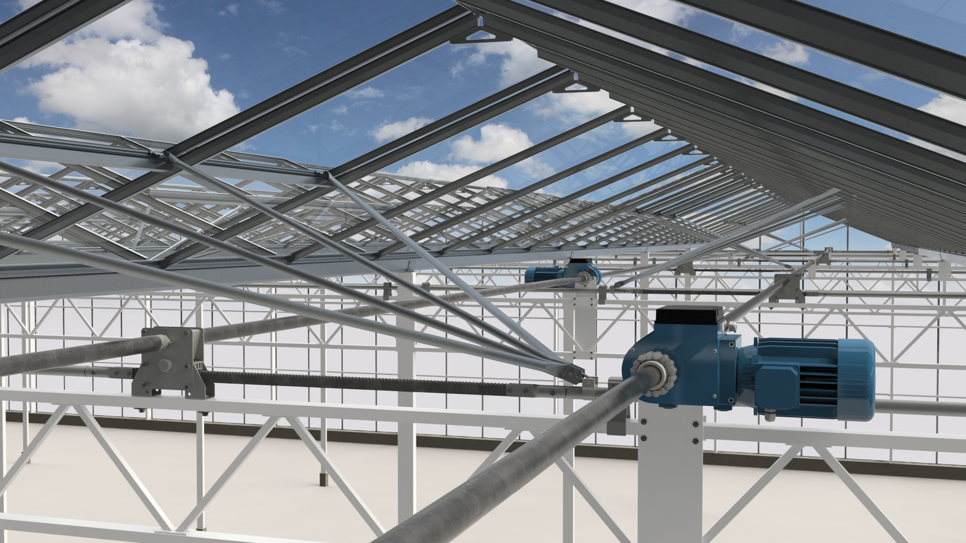
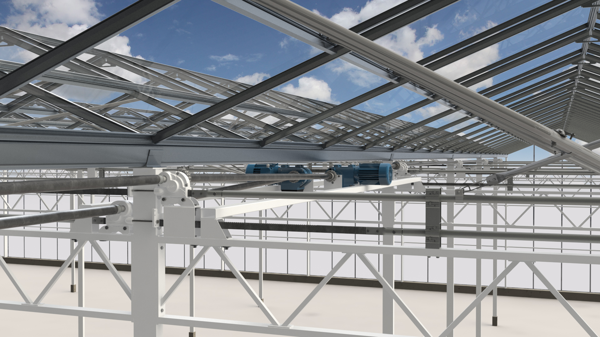
Get in contact with usTruss-rail ventilation systems are used for natural ventilation in Venlo greenhouses. With the R system, the rack boxes are attached to the truss. One gear rack moves a push-pull tube with push rods that operates one row of ventilation windows in a section. The lee- or wind-side ventilation gear racks are coupled with drive tubes and driven by a GW motor gearbox.
- Compact construction gives minimal shading.
- Easy installation on truss.
- Universal application, independent of column size.
- Suitable for 5/4" prefabricated drive shafts.
- Highly suitable for light and medium loads (5000/8500 N).
GW motor gearbox
| Article | Description | T (50/60Hz) [Nm] | n (50/60Hz) [rpm] | L [mm] | D [mm] | P (50/60Hz) [kW] | I (@ Y) (50/60Hz) [A] | I (@ Δ) (50/60Hz) [A] | m [kg] |
| P.GW10.3.400.26.KW | GW10 2.6 3ph 400V with CW+CH 10B z16 | 100 / 80 | 2,6 / 3,1 | 168 | 124 | 0,09 / 0,11 | 0,4 / 0,4 | 0,7 / 0,7 | 21 |
2 P.GW10.3.400.26.KW 11 GW10 2.6 3ph 400V with CW+CH 10B z16 12 13 P.GW10.400.26.KW.jpg 14 15 CAT_P.GW10.400.26.KW_2D.gif 17 16 10 | |||||||||
| P.GW10.3.400.52.KW | GW10 5.2 3ph 400V with CW+CH 10B z16 | 100 / 80 | 5,2 / 6,2 | 191 | 124 | 0,18 / 0,22 | 0,7 / 0,7 | 1,2 / 1,2 | 24 |
2 P.GW10.3.400.52.KW 11 GW10 5.2 3ph 400V with CW+CH 10B z16 12 13 P.GW10.400.26.KW.jpg 14 15 CAT_P.GW10.400.26.KW_2D.gif 17 16 10 | |||||||||
| P.GW30.400.26.KW | GW30 2.6 3ph 400V with CW+CH 10B z16 | 300 / 240 | 2,6 / 3,1 | 220 | 145 | 0,25 / 0,30 | 0,8 / 0,8 | 1,4 / 1,4 | 24 |
2 P.GW30.400.26.KW 11 GW30 2.6 3ph 400V with CW+CH 10B z16 12 13 P.GW30.400.26.KW.jpg 14 15 CAT_P.GW30.400.26.KW_2D.gif 17 16 10 | |||||||||
| P.GW30.400.52.KW | GW30 5.2 3ph 400V with CW+CH 10B z16 | 300 / 240 | 5,2 / 6,2 | 220 | 145 | 0,37 / 0,44 | 1,2 / 1,2 | 2,1 / 2,1 | 27 |
2 P.GW30.400.52.KW 11 GW30 5.2 3ph 400V with CW+CH 10B z16 12 13 P.GW30.400.26.KW.jpg 14 15 CAT_P.GW30.400.26.KW_2D.gif 17 16 10 | |||||||||
| P.GW40.400.26.KW | GW40 2.6 3ph 400V with CW+CH 10B z16 | 400 / 320 | 2,6 / 3,1 | 220 | 159 | 0,37 / 0,44 | 1,0 / 1,0 | 1,7 / 1,7 | 29 |
2 P.GW40.400.26.KW 11 GW40 2.6 3ph 400V with CW+CH 10B z16 12 13 P.GW80.400.26.KW.jpg 14 15 CAT_P.GW80.400.26.KW_2D.gif 17 16 10 | |||||||||
| P.GW40.3.400.52.KW | GW40 5.2 3ph 400V with CW+CH 10B z16 | 400 / 320 | 5,2 / 6,2 | 220 | 137 | 0,55 / 0,66 | 1,5 / 1,5 | 2,6 / 2,6 | 29 |
2 P.GW40.3.400.52.KW 11 GW40 5.2 3ph 400V with CW+CH 10B z16 12 13 P.GW80.400.26.KW.jpg 14 15 CAT_P.GW80.400.26.KW_2D.gif 17 16 10 | |||||||||
| P.GW80.400.26.KW | GW80 2.6 3ph 400V with CW+CH 10B z16 | 800 / 640 | 2,6 / 3,1 | 218 | 159 | 0,55 / 0,66 | 1,5 / 1,5 | 2,6 / 2,6 | 31 |
2 P.GW80.400.26.KW 11 GW80 2.6 3ph 400V with CW+CH 10B z16 12 13 P.GW80.400.26.KW.jpg 14 15 CAT_P.GW80.400.26.KW_2D.gif 17 16 10 | |||||||||
| P.GW80.2.400.40.KW | GW80 4.0 3ph 400V with CW+CH 10B z16 d25 | 800 / 640 | 4,0 / 4,8 | 242 | 159 | 0,75 / 0,90 | 2,0 / 2,0 | 3,5 / 3,5 | 38 |
2 P.GW80.2.400.40.KW 11 GW80 4.0 3ph 400V with CW+CH 10B z16 d25 12 13 P.GW80.400.26.KW.jpg 14 15 CAT_P.GW80.400.26.KW_2D.gif 17 16 10 | |||||||||
| P.GW100.400.26.KW | GW100 2.6 3ph 400V with CW+CH 12B z18 | 1000 / 800 | 2,6 / 3,1 | 242 | 159 | 0,75 / 0,90 | 2,2 / 2,2 | 3,8 / 3,8 | 38 |
2 P.GW100.400.26.KW 11 GW100 2.6 3ph 400V with CW+CH 12B z18 12 13 P.GW150S.400.40.KW.jpg 14 15 CAT_P.GW100.400.26.KW_2D.gif 17 16 10 |
Rack box
| Article | Description | F [N] | T [Nm] | i [-] | L [mm] | S [mm] | s [mm/rev] | n [rev] | m [kg] |
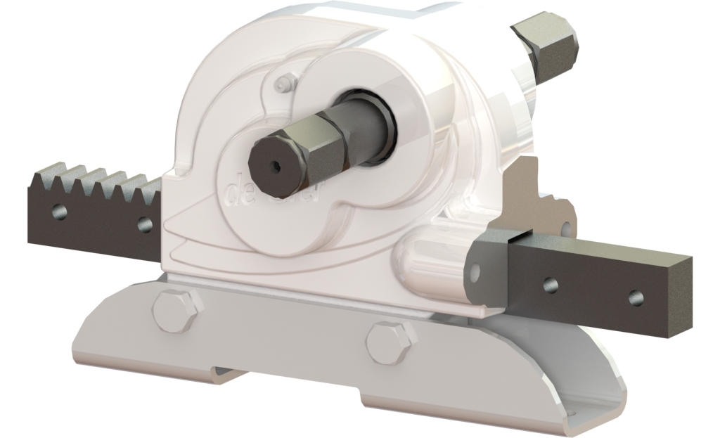
| P.THG25R.S0750 | THG25R, L1050 S0750mm | 5000 | 32,50 | 2,760 | 1050 | 750 | 36,35 | 21 | 9,0 |
2 P.THG25R.S0750 11 THG25R, L1050 S0750mm 12 13 P.THG25R.S0000.jpg 14 15 CAT_P.THG25R.S0000_2D.gif 16 17 10 | |||||||||
| P.THG25R.S0900 | THG25R, L1200 S0900mm | 5000 | 32,50 | 2,760 | 1200 | 900 | 36,35 | 25 | 9,5 |
2 P.THG25R.S0900 11 THG25R, L1200 S0900mm 12 13 P.THG25R.S0000.jpg 14 15 CAT_P.THG25R.S0000_2D.gif 16 17 10 | |||||||||
| P.THG25R.S1100 | THG25R L1400 S1100mm | 5000 | 32,50 | 2,760 | 1400 | 1100 | 36,35 | 31 | 10,0 |
2 P.THG25R.S1100 11 THG25R L1400 S1100mm 12 13 P.THG25R.S0000.jpg 14 15 CAT_P.THG25R.S0000_2D.gif 16 17 10 | |||||||||
| P.THG42R.S0750 | THG42R, L1050 S0750mm | 8500 | 55,25 | 2,760 | 1050 | 750 | 36,35 | 21 | 10,0 |
2 P.THG42R.S0750 11 THG42R, L1050 S0750mm 12 13 P.THG42R.S0000.jpg 14 15 CAT_P.THG42R.S0000_2D.gif 16 17 10 | |||||||||
| P.THG42R.S0900 | THG42R, L1200 S0900mm | 8500 | 55,25 | 2,760 | 1200 | 900 | 36,35 | 25 | 10,5 |
2 P.THG42R.S0900 11 THG42R, L1200 S0900mm 12 13 P.THG42R.S0000.jpg 14 15 CAT_P.THG42R.S0000_2D.gif 16 17 10 | |||||||||
| P.THG42R.S1100 | THG42R L1400 S1100mm | 8500 | 55,25 | 2,760 | 1400 | 1100 | 36,35 | 31 | 11,0 |
2 P.THG42R.S1100 11 THG42R L1400 S1100mm 12 13 P.THG42R.S0000.jpg 14 15 CAT_P.THG42R.S0000_2D.gif 16 17 10 |
Coupling set
| Article | Description | D [mm] | B [mm] | m [kg] |
| P.SKP.D27 | Coupling set D27 for THG25/42/55 rack | 27 | 15 / 20 | 0,2 |
| P.SKP.D32 | Coupling set D32 for THG25/42/55 rack | 32 | 15 / 20 | 0,2 |
Coupling set fastener
| Article | Description | B [mm] | m [kg] |
| P.SKP.BVM.15 | BVM coupling set - THG25 rack | 35 | 0,03 |
| P.SKP.BVM.20 | BVM coupling set - THG42/55 rack | 35 | 0,03 |
Locking
| Article | Description | m [kg] |
| P.AS-BORGCLIP | Axle securing clip | 0,01 |
Counter ring
| Article | Description | m [kg] |
| P.THG.CR | Contra-ring THG-serie ØD46,5 Ød11 d5 | 0,06 |
Slide bearing plate
| Article | Description | A [mm] | L [mm] | m [kg] |
| P.GL125.R.L220 | Slide bearing plate 5/4" R A165 L220 mm | 165 | 220 | 0,4 |
| P.GL125.R.L230 | Slide bearing plate 5/4" R A175 L230 mm | 175 | 230 | 0,4 |
Weld sprockets
| Article | Description | Chain | Shaft | Tmax [Nm] | Db [mm] | D [mm] | L [mm] | m [kg] |
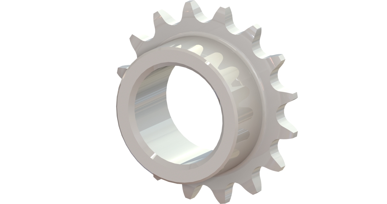
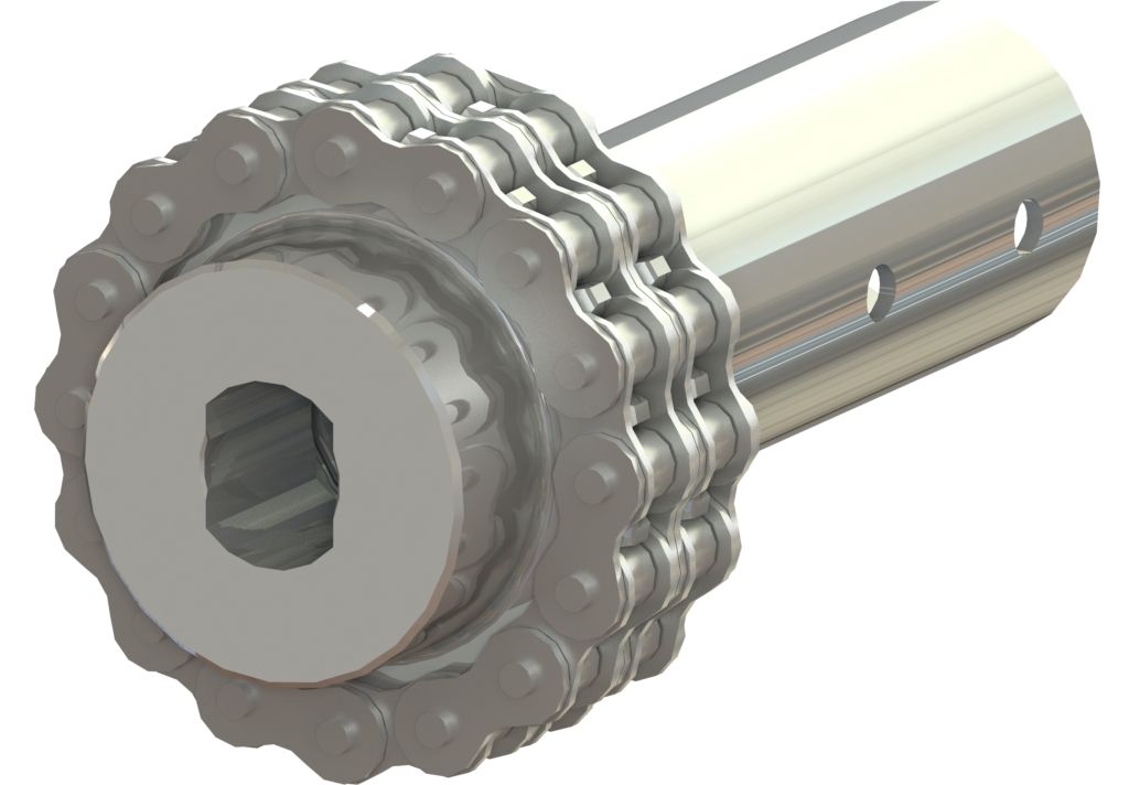
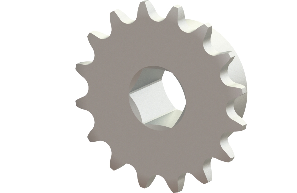
| P.LKWL10B.Z16.D125 | Weld sprocket 10B z16 - 5/4" | 10B z16 | D125 | 420 | 43 | 96 | 30 | 0,4 |
2 P.LKWL10B.Z16.D125 11 Weld sprocket 10B z16 - 5/4" 12 13 P.LKWL10B.Z16.D125.jpg 15 16 CAT_P.LKWL10B.Z16.D125_2D.gif 17 10 |
Chains
| Article | Description | Tmax [Nm] | D [mm] | m [kg] |
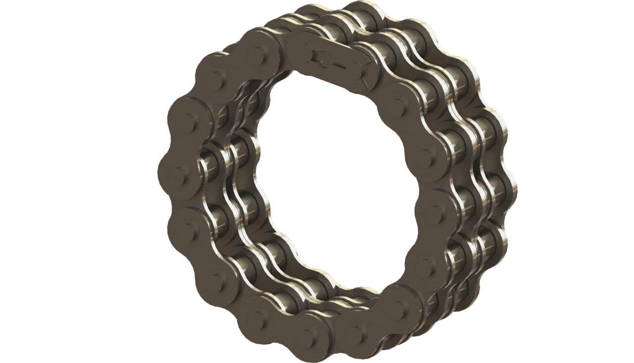
| P.KTG10B-2.Z16 | Chain 10B z16 | 420 | 96 | 0,5 |
| P.KTG12B-2.Z18 | Chain 12B z18 | 760 | 126 | 0,8 |
Sleeve joint coupling prefab
| Article | Description | Db [mm] | Type | m [kg] |
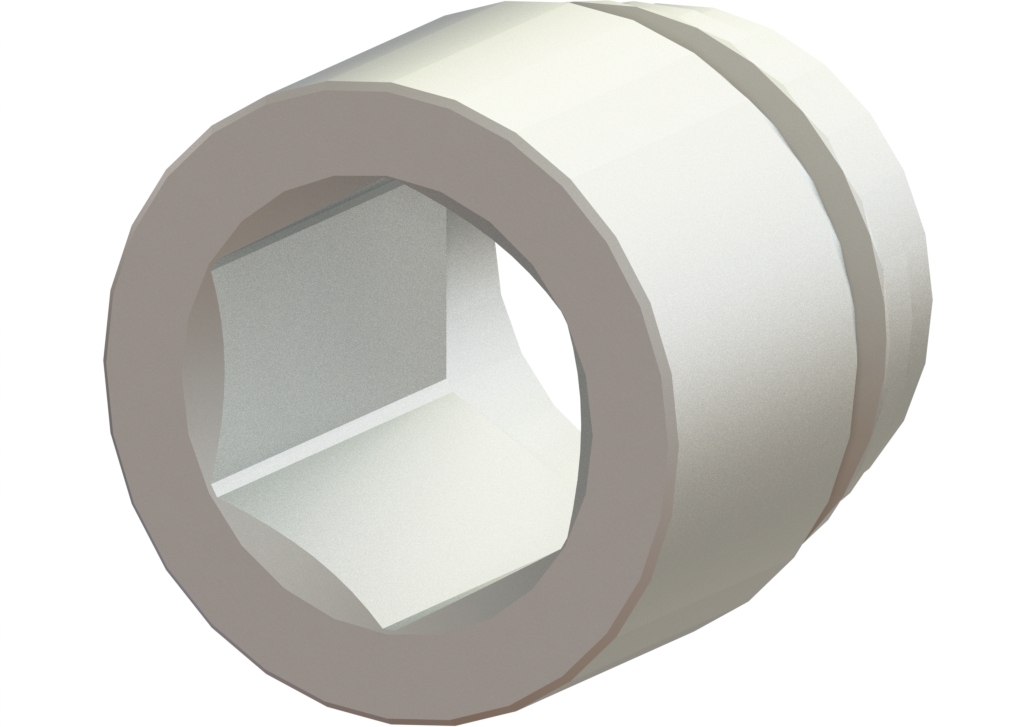
| P.SLKP125.S20 | Prefab sleeve joint coupling 5/4" - S20 | 42,4 | S20 | 0,2 |
Clamping mounting plates
| Article | Description | H [mm] | B [mm] | A [mm] | L [mm] | m [kg] |
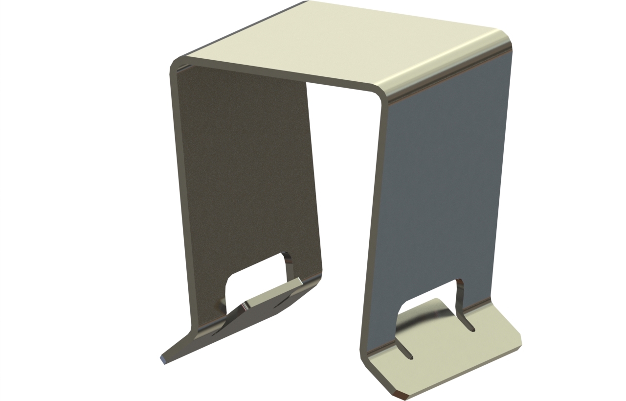
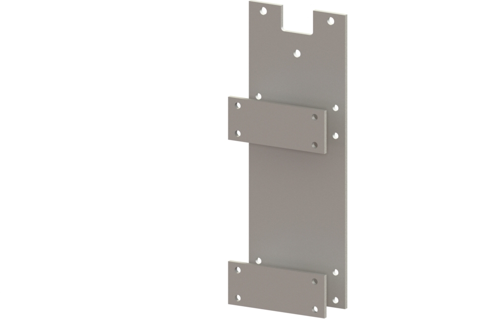
| P.MP.KL.350.25 | Clamping mounting plate 350 truss 25mm | 350 | 25 | 155 | 531 | 4,3 |
2 P.MP.KL.350.25 11 Clamping mounting plate 350 truss 25mm 12 13 P.MP.RK.KL.400.30.jpg 14 10 CAT_P.MP.KL.000.00_2D.gif | ||||||
| P.MP.KL.400.25 | Clamping mounting plate 400 truss 25mm | 400 | 25 | 155 | 581 | 4,7 |
2 P.MP.KL.400.25 11 Clamping mounting plate 400 truss 25mm 12 13 P.MP.RK.KL.400.30.jpg 14 10 CAT_P.MP.KL.000.00_2D.gif | ||||||
| P.MP.KL.400.30 | Clamping mounting plate 400 truss 30mm | 400 | 30 | 155 | 581 | 4,8 |
2 P.MP.KL.400.30 11 Clamping mounting plate 400 truss 30mm 12 13 P.MP.RK.KL.400.30.jpg 14 10 CAT_P.MP.KL.000.00_2D.gif | ||||||
| P.MP.KL.500.30 | Clamping mounting plate 500 truss 30mm | 500 | 30 | 155 | 681 | 5,5 |
2 P.MP.KL.500.30 11 Clamping mounting plate 500 truss 30mm 12 13 P.MP.RK.KL.400.30.jpg 14 10 CAT_P.MP.KL.000.00_2D.gif | ||||||
| P.MP.KL.600.30 | Clamping mounting plate 600 truss 30mm | 600 | 30 | 155 | 781 | 8,9 |
2 P.MP.KL.600.30 11 Clamping mounting plate 600 truss 30mm 12 13 P.MP.RK.KL.400.30.jpg 14 10 CAT_P.MP.KL.000.00_2D.gif |
Multiple options available upon request
Drive systems for ventilation
Rapidly varying weather conditions are the order of the day. The need for good, accurate ventilation systems and airtightness in larger production greenhouses is becoming increasingly important. New cultivation requires insights for less, accurate and metered ventilation in combination with more screens with the aim of keeping as much heat and moisture as possible in the greenhouse to save energy. To achieve an optimal climate through optimal ventilation, our drives are essential for optimal results.
End-wall ventilation in combination with R - P.THG25-42RGC
We are happy to help you with making a calculation
Get in contact with usEndwall truss-rail ventilation systems are used for extra ventilation in the endwall section. With the RGC system, the rack boxes are placed in line with the other gear racks and mounted on a C-profile between the gutters. These gear racks move one row of endwall ventilation windows in a section. They are connected to drive tubes with chain couplings for the necessary angle correction and driven by a GW motor gearbox. - Better climate in the endwall sections.
- Better climate in the head compartments.
- Very easy installation on standard C-profile.
- Suitable for 5/4" prefabricated drive shafts.
- Highly suitable for light and medium loads.
Rack box
| Article | Description | F [N] | T [Nm] | i [-] | L [mm] | S [mm] | s [mm/rev] | n [rev] | m [kg] |
| P.THG25RGC.S0750 | THG25RGC L1050 S0750mm | 5000 | 32,50 | 2,760 | 1050 | 750 | 36,35 | 21 | 8,0 |
2 P.THG25RGC.S0750 11 THG25RGC L1050 S0750mm 12 13 P.THG25RGC.S0000.jpg 14 15 CAT_P.THG25RKGC.S0000_2D.gif 16 17 10 | |||||||||
| P.THG25RGC.S0900 | THG25RGC L1200 S0900mm | 5000 | 32,50 | 2,760 | 1200 | 900 | 36,35 | 25 | 8,5 |
2 P.THG25RGC.S0900 11 THG25RGC L1200 S0900mm 12 13 P.THG25RGC.S0000.jpg 14 15 CAT_P.THG25RKGC.S0000_2D.gif 16 17 10 | |||||||||
| P.THG25RGC.S1100 | THG25RKC L1400 S1100mm | 5000 | 32,50 | 2,760 | 1400 | 1100 | 36,35 | 31 | 9,0 |
2 P.THG25RGC.S1100 11 THG25RKC L1400 S1100mm 12 13 P.THG25RGC.S0000.jpg 14 15 CAT_P.THG25RKGC.S0000_2D.gif 16 17 10 |
Coupling set
| Article | Description | D [mm] | B [mm] | m [kg] |
| P.SKP.D27 | Coupling set D27 for THG25/42/55 rack | 27 | 15 / 20 | 0,2 |
| P.SKP.D32 | Coupling set D32 for THG25/42/55 rack | 32 | 15 / 20 | 0,2 |
Coupling set fastener
| Article | Description | B [mm] | m [kg] |
| P.SKP.BVM.15 | BVM coupling set - THG25 rack | 35 | 0,03 |
Locking
| Article | Description | m [kg] |
| P.AS-BORGCLIP | Axle securing clip | 0,01 |
Slide bearing plate
| Article | Description | A [mm] | L [mm] | m [kg] |
| P.GL125.R.L220 | Slide bearing plate 5/4" R A165 L220 mm | 165 | 220 | 0,4 |
| P.GL125.R.L230 | Slide bearing plate 5/4" R A175 L230 mm | 175 | 230 | 0,4 |
Weld sprockets
| Article | Description | Chain | Shaft | Tmax [Nm] | Db [mm] | D [mm] | L [mm] | m [kg] |
| P.LKWL10B.Z16.D125 | Weld sprocket 10B z16 - 5/4" | 10B z16 | D125 | 420 | 43 | 96 | 30 | 0,4 |
2 P.LKWL10B.Z16.D125 11 Weld sprocket 10B z16 - 5/4" 12 13 P.LKWL10B.Z16.D125.jpg 15 16 CAT_P.LKWL10B.Z16.D125_2D.gif 17 10 |
Chains
| Article | Description | Tmax [Nm] | D [mm] | m [kg] |
| P.KTG10B-2.Z16 | Chain 10B z16 | 420 | 96 | 0,5 |
Tube bolt chain coupling on THG25RGC
| Article | Description | Tmax [Nm] | D2 [mm] | D3 [mm] | L1 [mm] | L3 [mm] | m [kg] |
| P.BBKK10B.S20.D125 | Tube bolt CC set 10B S20 z16 5/4" | 420 | 43,1 | 96 | 30 | 150 | 1,9 |
2 P.BBKK10B.S20.D125 13 Tube bolt CC set 10B S20 z16 5/4" 17 18 P.BBKK10B.S20.D000.jpg 20 21 CAT_P.BBKK10B.D00.D125_2D.gif 10 |
Drive systems for ventilation
Rapidly varying weather conditions are the order of the day. The need for good, accurate ventilation systems and airtightness in larger production greenhouses is becoming increasingly important. New cultivation requires insights for less, accurate and metered ventilation in combination with more screens with the aim of keeping as much heat and moisture as possible in the greenhouse to save energy. To achieve an optimal climate through optimal ventilation, our drives are essential for optimal results.
Truss-rail ventilation rail mounting - P.THG55R
We are happy to help you with making a calculation
Get in contact with usTruss-rail ventilation systems are used for natural ventilation in Venlo greenhouses. With the R system, the rack boxes are mounted on the truss. One gear rack moves a push-pull tube with push rods that operates one row of ventilation windows in a section. The lee- or wind-side ventilation gear racks are coupled with drive tubes and driven by a GW motor gearbox.
- Compact construction gives minimal shading.
- Easy installation on truss.
- Universal application, independent of column size.
- Suitable for 5/4" prefabricated drive shafts.
- Suitable for medium load (11,000 N).
GW motor gearbox
| Article | Description | T (50/60Hz) [Nm] | n (50/60Hz) [rpm] | L [mm] | D [mm] | P (50/60Hz) [kW] | I (@ Y) (50/60Hz) [A] | I (@ Δ) (50/60Hz) [A] | m [kg] |
| P.GW10.3.400.26.KW | GW10 2.6 3ph 400V with CW+CH 10B z16 | 100 / 80 | 2,6 / 3,1 | 168 | 124 | 0,09 / 0,11 | 0,4 / 0,4 | 0,7 / 0,7 | 21 |
2 P.GW10.3.400.26.KW 11 GW10 2.6 3ph 400V with CW+CH 10B z16 12 13 P.GW10.400.26.KW.jpg 14 15 CAT_P.GW10.400.26.KW_2D.gif 17 16 10 | |||||||||
| P.GW10.3.400.52.KW | GW10 5.2 3ph 400V with CW+CH 10B z16 | 100 / 80 | 5,2 / 6,2 | 191 | 124 | 0,18 / 0,22 | 0,7 / 0,7 | 1,2 / 1,2 | 24 |
2 P.GW10.3.400.52.KW 11 GW10 5.2 3ph 400V with CW+CH 10B z16 12 13 P.GW10.400.26.KW.jpg 14 15 CAT_P.GW10.400.26.KW_2D.gif 17 16 10 | |||||||||
| P.GW30.400.26.KW | GW30 2.6 3ph 400V with CW+CH 10B z16 | 300 / 240 | 2,6 / 3,1 | 220 | 145 | 0,25 / 0,30 | 0,8 / 0,8 | 1,4 / 1,4 | 24 |
2 P.GW30.400.26.KW 11 GW30 2.6 3ph 400V with CW+CH 10B z16 12 13 P.GW30.400.26.KW.jpg 14 15 CAT_P.GW30.400.26.KW_2D.gif 17 16 10 | |||||||||
| P.GW30.400.52.KW | GW30 5.2 3ph 400V with CW+CH 10B z16 | 300 / 240 | 5,2 / 6,2 | 220 | 145 | 0,37 / 0,44 | 1,2 / 1,2 | 2,1 / 2,1 | 27 |
2 P.GW30.400.52.KW 11 GW30 5.2 3ph 400V with CW+CH 10B z16 12 13 P.GW30.400.26.KW.jpg 14 15 CAT_P.GW30.400.26.KW_2D.gif 17 16 10 | |||||||||
| P.GW40.400.26.KW | GW40 2.6 3ph 400V with CW+CH 10B z16 | 400 / 320 | 2,6 / 3,1 | 220 | 159 | 0,37 / 0,44 | 1,0 / 1,0 | 1,7 / 1,7 | 29 |
2 P.GW40.400.26.KW 11 GW40 2.6 3ph 400V with CW+CH 10B z16 12 13 P.GW80.400.26.KW.jpg 14 15 CAT_P.GW80.400.26.KW_2D.gif 17 16 10 | |||||||||
| P.GW40.3.400.52.KW | GW40 5.2 3ph 400V with CW+CH 10B z16 | 400 / 320 | 5,2 / 6,2 | 220 | 137 | 0,55 / 0,66 | 1,5 / 1,5 | 2,6 / 2,6 | 29 |
2 P.GW40.3.400.52.KW 11 GW40 5.2 3ph 400V with CW+CH 10B z16 12 13 P.GW80.400.26.KW.jpg 14 15 CAT_P.GW80.400.26.KW_2D.gif 17 16 10 | |||||||||
| P.GW80.400.26.KW | GW80 2.6 3ph 400V with CW+CH 10B z16 | 800 / 640 | 2,6 / 3,1 | 218 | 159 | 0,55 / 0,66 | 1,5 / 1,5 | 2,6 / 2,6 | 31 |
2 P.GW80.400.26.KW 11 GW80 2.6 3ph 400V with CW+CH 10B z16 12 13 P.GW80.400.26.KW.jpg 14 15 CAT_P.GW80.400.26.KW_2D.gif 17 16 10 | |||||||||
| P.GW80.2.400.40.KW | GW80 4.0 3ph 400V with CW+CH 10B z16 d25 | 800 / 640 | 4,0 / 4,8 | 242 | 159 | 0,75 / 0,90 | 2,0 / 2,0 | 3,5 / 3,5 | 38 |
2 P.GW80.2.400.40.KW 11 GW80 4.0 3ph 400V with CW+CH 10B z16 d25 12 13 P.GW80.400.26.KW.jpg 14 15 CAT_P.GW80.400.26.KW_2D.gif 17 16 10 | |||||||||
| P.GW100.400.26.KW | GW100 2.6 3ph 400V with CW+CH 12B z18 | 1000 / 800 | 2,6 / 3,1 | 242 | 159 | 0,75 / 0,90 | 2,2 / 2,2 | 3,8 / 3,8 | 38 |
2 P.GW100.400.26.KW 11 GW100 2.6 3ph 400V with CW+CH 12B z18 12 13 P.GW150S.400.40.KW.jpg 14 15 CAT_P.GW100.400.26.KW_2D.gif 17 16 10 |
Rack box
| Article | Description | F [N] | T [Nm] | i [-] | L [mm] | S [mm] | s [mm/rev] | n [rev] | m [kg] |
| P.THG55R.1.S0750 | THG55R, L1050 S0750mm | 11000 | 65,00 | 3,125 | 1050 | 750 | 36,19 | 21 | 8,3 |
2 P.THG55R.1.S0750 11 THG55R, L1050 S0750mm 12 13 P.THG55R.1.S0000.jpg 14 15 CAT_P.THG55R.1.S0000_2D.gif 16 17 10 | |||||||||
| P.THG55R.1.S0900 | THG55R, L1200 S0900mm | 11000 | 65,00 | 3,125 | 1200 | 900 | 36,19 | 25 | 8,9 |
2 P.THG55R.1.S0900 11 THG55R, L1200 S0900mm 12 13 P.THG55R.1.S0000.jpg 14 15 CAT_P.THG55R.1.S0000_2D.gif 16 17 10 | |||||||||
| P.THG55R.1.S1100 | THG55R, L1400 S1100mm | 11000 | 65,00 | 3,125 | 1400 | 1100 | 36,19 | 31 | 9,7 |
2 P.THG55R.1.S1100 11 THG55R, L1400 S1100mm 12 13 P.THG55R.1.S0000.jpg 14 15 CAT_P.THG55R.1.S0000_2D.gif 16 17 10 |
Coupling set
| Article | Description | D [mm] | B [mm] | m [kg] |
| P.SKP.D27 | Coupling set D27 for THG25/42/55 rack | 27 | 15 / 20 | 0,2 |
| P.SKP.D32 | Coupling set D32 for THG25/42/55 rack | 32 | 15 / 20 | 0,2 |
Coupling set fastener
| Article | Description | B [mm] | m [kg] |
| P.SKP.BVM.20 | BVM coupling set - THG42/55 rack | 35 | 0,03 |
Locking
| Article | Description | m [kg] |
| P.ABR.24 | Shaft locking ring 24 DIN6799 EZ | 0,01 |
Counter ring
| Article | Description | m [kg] |
| P.THG.CR | Contra-ring THG-serie ØD46,5 Ød11 d5 | 0,06 |
Slide bearing plate
| Article | Description | A [mm] | L [mm] | m [kg] |
| P.GL125.R.L190 | Slide bearing plate 5/4" R A135 L190 mm | 135 | 190 | 0,3 |
| P.GL125.R.L195 | Slide bearing plate 5/4" R A140 L195 mm | 140 | 195 | 0,3 |
Weld sprockets
| Article | Description | Chain | Shaft | Tmax [Nm] | Db [mm] | D [mm] | L [mm] | m [kg] |
| P.LKWL10B.Z16.D125 | Weld sprocket 10B z16 - 5/4" | 10B z16 | D125 | 420 | 43 | 96 | 30 | 0,4 |
2 P.LKWL10B.Z16.D125 11 Weld sprocket 10B z16 - 5/4" 12 13 P.LKWL10B.Z16.D125.jpg 15 16 CAT_P.LKWL10B.Z16.D125_2D.gif 17 10 |
Chains
| Article | Description | Tmax [Nm] | D [mm] | m [kg] |
| P.KTG10B-2.Z16 | Chain 10B z16 | 420 | 96 | 0,5 |
| P.KTG12B-2.Z18 | Chain 12B z18 | 760 | 126 | 0,8 |
Sprockets on THG55R
| Article | Description | Chain | Shaft | Tmax [Nm] | D2 [mm] | L [mm] | m [kg] |
| P.KWL10B.Z16.ZK | Sleeve sprocket 10B z16 - ZK | 10B z16 | ZK | 420 | 96 | 30 | 0,6 |
2 P.KWL10B.Z16.ZK 11 Sleeve sprocket 10B z16 - ZK 12 13 P.KWL10B.Z16.ZK.jpg 14 15 CAT_P.KWL10B.Z16.ZK_2D.gif 10 |
Sleeve joint coupling prefab
| Article | Description | Db [mm] | Type | m [kg] |
| P.SLKP125.ZK | Prefab sleeve joint coupling 5/4" - ZK | 42,4 | ZK | 0,2 |
Clamping mounting plates
| Article | Description | H [mm] | B [mm] | A [mm] | L [mm] | m [kg] |
| P.MP.KL.350.25 | Clamping mounting plate 350 truss 25mm | 350 | 25 | 155 | 531 | 4,3 |
2 P.MP.KL.350.25 11 Clamping mounting plate 350 truss 25mm 12 13 P.MP.RK.KL.400.30.jpg 14 10 CAT_P.MP.KL.000.00_2D.gif | ||||||
| P.MP.KL.400.25 | Clamping mounting plate 400 truss 25mm | 400 | 25 | 155 | 581 | 4,7 |
2 P.MP.KL.400.25 11 Clamping mounting plate 400 truss 25mm 12 13 P.MP.RK.KL.400.30.jpg 14 10 CAT_P.MP.KL.000.00_2D.gif | ||||||
| P.MP.KL.400.30 | Clamping mounting plate 400 truss 30mm | 400 | 30 | 155 | 581 | 4,8 |
2 P.MP.KL.400.30 11 Clamping mounting plate 400 truss 30mm 12 13 P.MP.RK.KL.400.30.jpg 14 10 CAT_P.MP.KL.000.00_2D.gif | ||||||
| P.MP.KL.500.30 | Clamping mounting plate 500 truss 30mm | 500 | 30 | 155 | 681 | 5,5 |
2 P.MP.KL.500.30 11 Clamping mounting plate 500 truss 30mm 12 13 P.MP.RK.KL.400.30.jpg 14 10 CAT_P.MP.KL.000.00_2D.gif | ||||||
| P.MP.KL.600.30 | Clamping mounting plate 600 truss 30mm | 600 | 30 | 155 | 781 | 8,9 |
2 P.MP.KL.600.30 11 Clamping mounting plate 600 truss 30mm 12 13 P.MP.RK.KL.400.30.jpg 14 10 CAT_P.MP.KL.000.00_2D.gif |
Multiple options available upon request
Drive systems for ventilation
Rapidly varying weather conditions are the order of the day. The need for good, accurate ventilation systems and airtightness in larger production greenhouses is becoming increasingly important. New cultivation requires insights for less, accurate and metered ventilation in combination with more screens with the aim of keeping as much heat and moisture as possible in the greenhouse to save energy. To achieve an optimal climate through optimal ventilation, our drives are essential for optimal results.
End-wall ventilation in combination with R - P.THG55RGC
We are happy to help you with making a calculation
Get in contact with usEndwall truss-rail ventilation systems are used for extra ventilation in the endwall section. With the RGC system, the rack boxes are placed in line with the other gear racks and mounted on a C-profile between the gutters. These gear racks move one row of endwall ventilation windows in a section. They are connected to drive tubes with chain couplings for the necessary angle correction and driven by a GW motor gearbox. - Better climate in the endwall sections.
- Better climate in the head compartments.
- Very easy installation on standard C-profile.
- Suitable for 5/4" prefabricated drive shafts.
- Highly suitable for medium load in combination with THG55R.
Rack box
| Article | Description | F [N] | T [Nm] | i [-] | L [mm] | S [mm] | s [mm/rev] | n [rev] | m [kg] |
| P.THG55RGC.1.S0750 | THG55RGC, L1050 S0750mm | 11000 | 65,00 | 3,125 | 1050 | 750 | 36,19 | 21 | 9,2 |
2 P.THG55RGC.1.S0750 11 THG55RGC, L1050 S0750mm 12 13 P.THG55RGC.1.S0000.jpg 14 15 CAT_P.THG55RGC.1.S0000_2D.gif 16 17 10 | |||||||||
| P.THG55RGC.1.S0900 | THG55RGC, L1200 S0900mm | 11000 | 65,00 | 3,125 | 1200 | 900 | 36,19 | 25 | 9,8 |
2 P.THG55RGC.1.S0900 11 THG55RGC, L1200 S0900mm 12 13 P.THG55RGC.1.S0000.jpg 14 15 CAT_P.THG55RGC.1.S0000_2D.gif 16 17 10 | |||||||||
| P.THG55RGC.1.S1100 | THG55RGC, L1400 S1100mm | 11000 | 65,00 | 3,125 | 1400 | 1100 | 36,19 | 31 | 10,6 |
2 P.THG55RGC.1.S1100 11 THG55RGC, L1400 S1100mm 12 13 P.THG55RGC.1.S0000.jpg 14 15 CAT_P.THG55RGC.1.S0000_2D.gif 16 17 10 |
Coupling set
| Article | Description | D [mm] | B [mm] | m [kg] |
| P.SKP.D27 | Coupling set D27 for THG25/42/55 rack | 27 | 15 / 20 | 0,2 |
| P.SKP.D32 | Coupling set D32 for THG25/42/55 rack | 32 | 15 / 20 | 0,2 |
Coupling set fastener
| Article | Description | B [mm] | m [kg] |
| P.SKP.BVM.20 | BVM coupling set - THG42/55 rack | 35 | 0,03 |
Locking
| Article | Description | m [kg] |
| P.ABR.24 | Shaft locking ring 24 DIN6799 EZ | 0,01 |
Slide bearing plate
| Article | Description | A [mm] | L [mm] | m [kg] |
| P.GL125.R.L190 | Slide bearing plate 5/4" R A135 L190 mm | 135 | 190 | 0,3 |
| P.GL125.R.L195 | Slide bearing plate 5/4" R A140 L195 mm | 140 | 195 | 0,3 |
Weld sprockets
| Article | Description | Chain | Shaft | Tmax [Nm] | Db [mm] | D [mm] | L [mm] | m [kg] |
| P.LKWL10B.Z16.D125 | Weld sprocket 10B z16 - 5/4" | 10B z16 | D125 | 420 | 43 | 96 | 30 | 0,4 |
2 P.LKWL10B.Z16.D125 11 Weld sprocket 10B z16 - 5/4" 12 13 P.LKWL10B.Z16.D125.jpg 15 16 CAT_P.LKWL10B.Z16.D125_2D.gif 17 10 |
Chains
| Article | Description | Tmax [Nm] | D [mm] | m [kg] |
| P.KTG10B-2.Z16 | Chain 10B z16 | 420 | 96 | 0,5 |
Tube bolt chain coupling on THG55RGC
| Article | Description | Tmax [Nm] | D2 [mm] | D3 [mm] | L1 [mm] | L3 [mm] | m [kg] |
| P.BBKK10B.ZK.D125 | Tube bolt CC set 10B ZK z16 5/4" | 420 | 43,1 | 96 | 30 | 150 | 1,9 |
2 P.BBKK10B.ZK.D125 13 Tube bolt CC set 10B ZK z16 5/4" 17 18 P.BBKK10B.ZK.D000.jpg 20 21 CAT_P.BBKK10B.D00.D125_2D.gif 10 |
Drive systems for ventilation
Rapidly varying weather conditions are the order of the day. The need for good, accurate ventilation systems and airtightness in larger production greenhouses is becoming increasingly important. New cultivation requires insights for less, accurate and metered ventilation in combination with more screens with the aim of keeping as much heat and moisture as possible in the greenhouse to save energy. To achieve an optimal climate through optimal ventilation, our drives are essential for optimal results.
Truss-rail ventilation rail mounting - P.THG76R
We are happy to help you with making a calculation
Get in contact with usTruss-rail ventilation systems are used for natural ventilation in Venlo greenhouses. With the R system, the rack boxes are mounted on the truss. One gear rack moves a push-pull tube with push rods that operates one row of ventilation windows in a section. The lee- or wind-side ventilation gear racks are coupled with drive tubes and driven by a GW motor gearbox.
- Maximum light yield, minimum shadow.
- Easy installation on truss.
- Universal application, independent of column size.
- Suitable for 5/4" prefabricated drive shafts.
- Highly suitable for heavy load (15,000 N).
GW motor gearbox
| Article | Description | T (50/60Hz) [Nm] | n (50/60Hz) [rpm] | L [mm] | D [mm] | P (50/60Hz) [kW] | I (@ Y) (50/60Hz) [A] | I (@ Δ) (50/60Hz) [A] | m [kg] |
| P.GW10.3.400.26.KW | GW10 2.6 3ph 400V with CW+CH 10B z16 | 100 / 80 | 2,6 / 3,1 | 168 | 124 | 0,09 / 0,11 | 0,4 / 0,4 | 0,7 / 0,7 | 21 |
2 P.GW10.3.400.26.KW 11 GW10 2.6 3ph 400V with CW+CH 10B z16 12 13 P.GW10.400.26.KW.jpg 14 15 CAT_P.GW10.400.26.KW_2D.gif 17 16 10 | |||||||||
| P.GW10.3.400.52.KW | GW10 5.2 3ph 400V with CW+CH 10B z16 | 100 / 80 | 5,2 / 6,2 | 191 | 124 | 0,18 / 0,22 | 0,7 / 0,7 | 1,2 / 1,2 | 24 |
2 P.GW10.3.400.52.KW 11 GW10 5.2 3ph 400V with CW+CH 10B z16 12 13 P.GW10.400.26.KW.jpg 14 15 CAT_P.GW10.400.26.KW_2D.gif 17 16 10 | |||||||||
| P.GW30.400.26.KW | GW30 2.6 3ph 400V with CW+CH 10B z16 | 300 / 240 | 2,6 / 3,1 | 220 | 145 | 0,25 / 0,30 | 0,8 / 0,8 | 1,4 / 1,4 | 24 |
2 P.GW30.400.26.KW 11 GW30 2.6 3ph 400V with CW+CH 10B z16 12 13 P.GW30.400.26.KW.jpg 14 15 CAT_P.GW30.400.26.KW_2D.gif 17 16 10 | |||||||||
| P.GW30.400.52.KW | GW30 5.2 3ph 400V with CW+CH 10B z16 | 300 / 240 | 5,2 / 6,2 | 220 | 145 | 0,37 / 0,44 | 1,2 / 1,2 | 2,1 / 2,1 | 27 |
2 P.GW30.400.52.KW 11 GW30 5.2 3ph 400V with CW+CH 10B z16 12 13 P.GW30.400.26.KW.jpg 14 15 CAT_P.GW30.400.26.KW_2D.gif 17 16 10 | |||||||||
| P.GW40.400.26.KW | GW40 2.6 3ph 400V with CW+CH 10B z16 | 400 / 320 | 2,6 / 3,1 | 220 | 159 | 0,37 / 0,44 | 1,0 / 1,0 | 1,7 / 1,7 | 29 |
2 P.GW40.400.26.KW 11 GW40 2.6 3ph 400V with CW+CH 10B z16 12 13 P.GW80.400.26.KW.jpg 14 15 CAT_P.GW80.400.26.KW_2D.gif 17 16 10 | |||||||||
| P.GW40.3.400.52.KW | GW40 5.2 3ph 400V with CW+CH 10B z16 | 400 / 320 | 5,2 / 6,2 | 220 | 137 | 0,55 / 0,66 | 1,5 / 1,5 | 2,6 / 2,6 | 29 |
2 P.GW40.3.400.52.KW 11 GW40 5.2 3ph 400V with CW+CH 10B z16 12 13 P.GW80.400.26.KW.jpg 14 15 CAT_P.GW80.400.26.KW_2D.gif 17 16 10 | |||||||||
| P.GW80.400.26.KW | GW80 2.6 3ph 400V with CW+CH 10B z16 | 800 / 640 | 2,6 / 3,1 | 218 | 159 | 0,55 / 0,66 | 1,5 / 1,5 | 2,6 / 2,6 | 31 |
2 P.GW80.400.26.KW 11 GW80 2.6 3ph 400V with CW+CH 10B z16 12 13 P.GW80.400.26.KW.jpg 14 15 CAT_P.GW80.400.26.KW_2D.gif 17 16 10 | |||||||||
| P.GW80.2.400.40.KW | GW80 4.0 3ph 400V with CW+CH 10B z16 d25 | 800 / 640 | 4,0 / 4,8 | 242 | 159 | 0,75 / 0,90 | 2,0 / 2,0 | 3,5 / 3,5 | 38 |
2 P.GW80.2.400.40.KW 11 GW80 4.0 3ph 400V with CW+CH 10B z16 d25 12 13 P.GW80.400.26.KW.jpg 14 15 CAT_P.GW80.400.26.KW_2D.gif 17 16 10 | |||||||||
| P.GW100.400.26.KW | GW100 2.6 3ph 400V with CW+CH 12B z18 | 1000 / 800 | 2,6 / 3,1 | 242 | 159 | 0,75 / 0,90 | 2,2 / 2,2 | 3,8 / 3,8 | 38 |
2 P.GW100.400.26.KW 11 GW100 2.6 3ph 400V with CW+CH 12B z18 12 13 P.GW150S.400.40.KW.jpg 14 15 CAT_P.GW100.400.26.KW_2D.gif 17 16 10 |
Rack box
| Article | Description | F [N] | T [Nm] | i [-] | L [mm] | S [mm] | s [mm/rev] | n [rev] | m [kg] |
| P.THG76R.1.S0730 | THG76R 15kN m4, L1100 S0730mm | 15000 | 60,50 | 6,000 | 1100 | 730 | 23 | 33 | 12,3 |
2 P.THG76R.1.S0730 11 THG76R 15kN m4, L1100 S0730mm 12 13 P.THG76R.1.S0000.jpg 14 15 CAT_P.THG76R.1.S0000_2D.gif 16 17 10 | |||||||||
| P.THG76R.1.S0880 | THG76R 15kN m4, L1250 S0880mm | 15000 | 60,50 | 6,000 | 1250 | 880 | 23 | 39 | 13,1 |
2 P.THG76R.1.S0880 11 THG76R 15kN m4, L1250 S0880mm 12 13 P.THG76R.1.S0000.jpg 14 15 CAT_P.THG76R.1.S0000_2D.gif 16 17 10 | |||||||||
| P.THG76R.1.S1030 | THG76R 15kN m4, L1400 S1030mm | 15000 | 60,50 | 6,000 | 1400 | 1030 | 23 | 48 | 13,8 |
2 P.THG76R.1.S1030 11 THG76R 15kN m4, L1400 S1030mm 12 13 P.THG76R.1.S0000.jpg 14 15 CAT_P.THG76R.1.S0000_2D.gif 16 17 10 |
Coupling set
Coupling set fastener
| Article | Description | B [mm] | m [kg] |
| P.SKP.BVM.25 | BVM coupling set - THG76 rack | 40 | 0,03 |
Locking
| Article | Description | m [kg] |
| P.ABR.24 | Shaft locking ring 24 DIN6799 EZ | 0,01 |
Counter ring
| Article | Description | m [kg] |
| P.THG.CR | Contra-ring THG-serie ØD46,5 Ød11 d5 | 0,06 |
Slide bearing plate
| Article | Description | A [mm] | L [mm] | m [kg] |
| P.GL125.R.L190 | Slide bearing plate 5/4" R A135 L190 mm | 135 | 190 | 0,3 |
| P.GL125.R.L195 | Slide bearing plate 5/4" R A140 L195 mm | 140 | 195 | 0,3 |
Weld sprockets
| Article | Description | Chain | Shaft | Tmax [Nm] | Db [mm] | D [mm] | L [mm] | m [kg] |
| P.LKWL10B.Z16.D125 | Weld sprocket 10B z16 - 5/4" | 10B z16 | D125 | 420 | 43 | 96 | 30 | 0,4 |
2 P.LKWL10B.Z16.D125 11 Weld sprocket 10B z16 - 5/4" 12 13 P.LKWL10B.Z16.D125.jpg 15 16 CAT_P.LKWL10B.Z16.D125_2D.gif 17 10 |
Chains
| Article | Description | Tmax [Nm] | D [mm] | m [kg] |
| P.KTG10B-2.Z16 | Chain 10B z16 | 420 | 96 | 0,5 |
| P.KTG12B-2.Z18 | Chain 12B z18 | 760 | 126 | 0,8 |
Sleeve sprockets on THG76R
| Article | Description | Chain | Shaft | Tmax [Nm] | D2 [mm] | L [mm] | m [kg] |
| P.KWL10B.Z16.ZK | Sleeve sprocket 10B z16 - ZK | 10B z16 | ZK | 420 | 96 | 30 | 0,6 |
2 P.KWL10B.Z16.ZK 11 Sleeve sprocket 10B z16 - ZK 12 13 P.KWL10B.Z16.ZK.jpg 14 15 CAT_P.KWL10B.Z16.ZK_2D.gif 10 |
Sleeve joint coupling prefab
| Article | Description | Db [mm] | Type | m [kg] |
| P.SLKP125.ZK | Prefab sleeve joint coupling 5/4" - ZK | 42,4 | ZK | 0,2 |
Clamping mounting plates
| Article | Description | H [mm] | B [mm] | A [mm] | L [mm] | m [kg] |
| P.MP.KL.350.25 | Clamping mounting plate 350 truss 25mm | 350 | 25 | 155 | 531 | 4,3 |
2 P.MP.KL.350.25 11 Clamping mounting plate 350 truss 25mm 12 13 P.MP.RK.KL.400.30.jpg 14 10 CAT_P.MP.KL.000.00_2D.gif | ||||||
| P.MP.KL.400.25 | Clamping mounting plate 400 truss 25mm | 400 | 25 | 155 | 581 | 4,7 |
2 P.MP.KL.400.25 11 Clamping mounting plate 400 truss 25mm 12 13 P.MP.RK.KL.400.30.jpg 14 10 CAT_P.MP.KL.000.00_2D.gif | ||||||
| P.MP.KL.400.30 | Clamping mounting plate 400 truss 30mm | 400 | 30 | 155 | 581 | 4,8 |
2 P.MP.KL.400.30 11 Clamping mounting plate 400 truss 30mm 12 13 P.MP.RK.KL.400.30.jpg 14 10 CAT_P.MP.KL.000.00_2D.gif | ||||||
| P.MP.KL.500.30 | Clamping mounting plate 500 truss 30mm | 500 | 30 | 155 | 681 | 5,5 |
2 P.MP.KL.500.30 11 Clamping mounting plate 500 truss 30mm 12 13 P.MP.RK.KL.400.30.jpg 14 10 CAT_P.MP.KL.000.00_2D.gif | ||||||
| P.MP.KL.600.30 | Clamping mounting plate 600 truss 30mm | 600 | 30 | 155 | 781 | 8,9 |
2 P.MP.KL.600.30 11 Clamping mounting plate 600 truss 30mm 12 13 P.MP.RK.KL.400.30.jpg 14 10 CAT_P.MP.KL.000.00_2D.gif |
Multiple options available upon request
Drive systems for ventilation
Rapidly varying weather conditions are the order of the day. The need for good, accurate ventilation systems and airtightness in larger production greenhouses is becoming increasingly important. New cultivation requires insights for less, accurate and metered ventilation in combination with more screens with the aim of keeping as much heat and moisture as possible in the greenhouse to save energy. To achieve an optimal climate through optimal ventilation, our drives are essential for optimal results.
End-wall ventilation in combination with R - P.THG76RGC
We are happy to help you with making a calculation
Get in contact with usEndwall truss-rail ventilation systems are used for extra ventilation in the endwall section. With the RGC system, the rack boxes are placed in line with the other gear racks and mounted on a C-profile between the gutters. These gear racks move one row of endwall ventilation windows in a section. They are connected to drive tubes with chain couplings for the necessary angle correction and driven by a GW motor gearbox.
- Better climate in the head compartments.
- Very easy installation on standard C-profile.
- Suitable for 5/4" prefabricated drive shafts.
- Highly suitable for heavy load in combination with THG76R.
Rack box
| Article | Description | F [N] | T [Nm] | i [-] | L [mm] | S [mm] | s [mm/rev] | n [rev] | m [kg] |
| P.THG76RGC.1.S0730 | THG76RGC 15kN m4, L1100 S0730mm | 15000 | 60,50 | 6,000 | 1100 | 730 | 23 | 33 | 14,0 |
2 P.THG76RGC.1.S0730 11 THG76RGC 15kN m4, L1100 S0730mm 12 13 P.THG76RGC.1.S0000.jpg 14 15 CAT_P.THG76RGC.1.S0000_2D.gif 16 17 10 | |||||||||
| P.THG76RGC.1.S0880 | THG76RGC 15kN m4, L1250 S0880mm | 15000 | 60,50 | 6,000 | 1250 | 880 | 23 | 39 | 14,8 |
2 P.THG76RGC.1.S0880 11 THG76RGC 15kN m4, L1250 S0880mm 12 13 P.THG76RGC.1.S0000.jpg 14 15 CAT_P.THG76RGC.1.S0000_2D.gif 16 17 10 | |||||||||
| P.THG76RKGC.1.S1050 | THG76RKGC 15kN m4, L1550 S1050mm | 15000 | 60,50 | 6,000 | 1550 | 1050 | 23 | 48 | 15,9 |
2 P.THG76RKGC.1.S1050 11 THG76RKGC 15kN m4, L1550 S1050mm 12 13 P.THG76RKGC.1.S0000.jpg 14 15 CAT_P.THG76RKGC.1.S0000_2D.gif 16 17 10 |
Coupling set
Coupling set fastener
| Article | Description | B [mm] | m [kg] |
| P.SKP.BVM.25 | BVM coupling set - THG76 rack | 40 | 0,03 |
Locking
| Article | Description | m [kg] |
| P.ABR.24 | Shaft locking ring 24 DIN6799 EZ | 0,01 |
Slide bearing plate
| Article | Description | A [mm] | L [mm] | m [kg] |
| P.GL125.R.L190 | Slide bearing plate 5/4" R A135 L190 mm | 135 | 190 | 0,3 |
| P.GL125.R.L195 | Slide bearing plate 5/4" R A140 L195 mm | 140 | 195 | 0,3 |
Weld sprockets
| Article | Description | Chain | Shaft | Tmax [Nm] | Db [mm] | D [mm] | L [mm] | m [kg] |
| P.LKWL10B.Z16.D125 | Weld sprocket 10B z16 - 5/4" | 10B z16 | D125 | 420 | 43 | 96 | 30 | 0,4 |
2 P.LKWL10B.Z16.D125 11 Weld sprocket 10B z16 - 5/4" 12 13 P.LKWL10B.Z16.D125.jpg 15 16 CAT_P.LKWL10B.Z16.D125_2D.gif 17 10 |
Chains
| Article | Description | Tmax [Nm] | D [mm] | m [kg] |
| P.KTG10B-2.Z16 | Chain 10B z16 | 420 | 96 | 0,5 |
Tube bolt chain coupling on THG76RGC
| Article | Description | Tmax [Nm] | D2 [mm] | D3 [mm] | L1 [mm] | L3 [mm] | m [kg] |
| P.BBKK10B.ZK.D125 | Tube bolt CC set 10B ZK z16 5/4" | 420 | 43,1 | 96 | 30 | 150 | 1,9 |
2 P.BBKK10B.ZK.D125 13 Tube bolt CC set 10B ZK z16 5/4" 17 18 P.BBKK10B.ZK.D000.jpg 20 21 CAT_P.BBKK10B.D00.D125_2D.gif 10 |
Drive systems for ventilation
Rapidly varying weather conditions are the order of the day. The need for good, accurate ventilation systems and airtightness in larger production greenhouses is becoming increasingly important. New cultivation requires insights for less, accurate and metered ventilation in combination with more screens with the aim of keeping as much heat and moisture as possible in the greenhouse to save energy. To achieve an optimal climate through optimal ventilation, our drives are essential for optimal results.

De Gier Drive Systems
+ 31 174 29 20 89

